Water meters for the collector and drainage network
Water metering in the collector and drainage network is carried out in open drains and collectors. Gauging stations are installed at the outfalls of the end of sections lower-order drains that inflow to higher-order drains.
In large inter-farm collectors, reference (transit) gauging stations are installed on.
The feature of water metering in the open collector and drainage network (CDN) is as follows:
• gentle slopes and low flow velocity;
• change in the hydraulic regime during the growing season as a result of channel overgrowing with weed and aquatic vegetation;
• dulling of the slopes as a result of high fluctuation of the drainage modulus during the growing and non-growing seasons at water evacuation after leaching of saline lands;
Taking into account the above-listed features for metering CDN water, the following water meters are recommended by the practical hydrometry:
• gauging station of fixed-channel type with concrete cover (FCCC);
• gauging station of asymmetrical-section fixed-channel type (FCAS);
• SANIIRI nozzles (SN);
• SANIIRI twin nozzles (STN)
FCCC type gauging station
As was mentioned above, one of the features of CDN is dulling of the slopes and change of the canal cross-section shape with time, which does not meet gauging station requirements. As such, to make the regular time-invariable cross-section of the canal with, the part of the collector earth bed at the site of a planned gauging station is encasing with concrete cover/strip. The concrete cover width is taken equal to the canal depth at a maximum level, but not less than 3-5 m. The concrete cover should be lifted above the canal depth to a value р = 0,05-0,2 * Нmax.
The FCCC type gauging station calibration and operation methods are similar to that of fixed-channel calibration in the irrigation network.
FCAC type gauging station
Open collectors and drains, where low-rate (up to 50 l/s) water runs, are recommended to be equipped with FCAC type gauging stations.
The length of the faced section is taken equal to Lf = 5-10. The height of the fixed section hfis taken more by 0.3-0.4 m than the maximum water level. Contracted and asymmetric channel cross-section will create the depth and flow velocity required for measuring water flow rate.
Check measurement of flow rate is carried out at the gauging footbridge. Here, water metering is similar to the well-known method of obtaining of the unique dependence Q = f(H) by calibration of FCAC type gauging stations by the velocity-area method.
SN type water meters
For the open drainage network with a discharge of up to 250 l/s, circular or rectangular cross-section SN type nozzles are recommended as follows:
• SN type water meter “10 х 20” is designed for open drains with discharges from 10 to 40 l/s;
• SN type water meter “25 х 50” is designed for open drains with discharges from 60 to 250 l/s.
SN type water meters are made from wood planks or steel sheets. The SN type water meter structure is composed of the wall into which a cone nozzle is built aflush at the center at a certain elevation.
When making a SN type water meter from metal, its facets are welded butt-jointed (T-butt welding) so that the inside welds should be clean with no leakage.
The outlet cross-section is made to a tolerance of + 2 mm, while the other dimensions to a tolerance of + 5–10 mm.
The nozzle axis should be perpendicular to the wall and is given three coats of anticorrosive paint. Level gage rods are installed at the both sides of the wall on the same level as the zero level. The wall dimensions are set such that to embed it into the canal cross section.
Water flow rate is determined from the relationship:
where:
4.1 is a constant coefficient;
а is the height of the outlet cross-section, m;
b is the width of the outlet cross-section, m;
Z = H-h (difference of level) drop, m.
For the convenience of specification of the water flow rate through SN type water meters, the water flow rate values depending on the difference of the water levels upstream and downstream are given in the tabular form.
The nozzle installation and operation requirements are as follows:
• the nozzles get cut into the canal slopes with stop of the nozzle’s lower edge against the bottom so that the water level downstream even at minimum flow rate should be higher than the outlet upper edge of the nozzle, i.e. the latter should be in submerged regime;
• in any case, the nozzle wall should be installed upright and coincide with the canal axis;
• the nozzle framework is rammed down to the bottom and slopes to prevent bottom and lateral water seepage. The ground of the slopes and bottom of the upstream and downstream sections of the canal is stabilized with local materials.
STN type water meters»
To measure the flow rate in open collectors with high discharge, STN type water meters are installed.
The STN type water meter structure consists of the wall into which two circular or rectangular-section SANIIRI nozzles are built aflush at a certain elevation. A gauging footbridge is mounted on the wall top for reading from two level gage rods. Its entire construction is composed from metal and installed across the channel in a gently sloping pit which provides flooding of the nozzle hole from the downstream at a minimum flow rate.
The wall should have dimensions with allowances made for embedding of it into the collector bed and slopes to a depth of not less than 0.5 m. The wall height should be higher than the maximum water level by 0.3-0.4 m.
The discharge in a STN type water meter is determined from the above-cited SN type water meter relation multiplied by the number of nozzles.
Metering of the flow rate in vertical drainage wells
The flow rate in pressure pipelines, artesian wells and vertical drainage wells (VDW) is measured by means of ultrasonic, induction, electromagnetic, partial (bypass-water) and other type flow meters. At present, the population of these devices installed in VDWs has become outdated and out-of-service.
In case of need to measure the flow rate of VDW, it is recommended to be equipped with one of standard flow meters, e.g. by a SANIIRI flume.
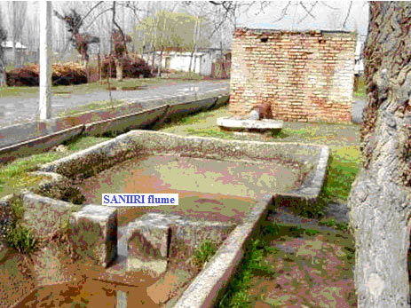
Technical standards
