Water metering implies a system of measurements and record of water volume at irrigation & drainage and water management facilities. Water metering allows controlling water resources use and forms the core of the centralized control of water distribution and water supply in irrigation systems.
According to functional features, the inter-farm part of the system includes the site of head water supply, commanding and water distribution nodes, and water delivery points to farms; the on-farm part of the system includes on-farm water distribution nodes, water delivery points to crop-rotation land plots.
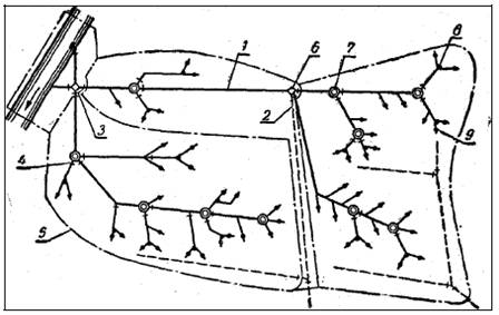
Scheme of water distribution and water accounting in the irrigation system:
1 – canals; 2 – collectors; 3 – main gauging station; 4 – gauging stations; 5 – boundaries of producing sites;
6 – commanding nodes; 7 – distribution nodes; 8 – automatic nodes; 9 – water delivery points
The section of head water supply with water intake by pumping includes a pumping station, pressure pipeline, and stilling pool; with gravity water intake – head water intake structure, upstream section of the main canal down to the main gauging station. In both cases, the head water supply section includes a reach of river or reservoir with special structures (weir, dams, mountings, etc.) and supporting gauging station on the irrigation source for determination and accounting of water resources as well as the main hydrometric post at the head of the main canal for accounting of water intake to the system.
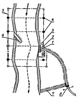
Equipping of the head reach with maintenance facilities:
1 – head regulator; 2 – cross section of connection; 3 – main benchmark; 4 – streambed cross section;
5 – boundary of production sites; 6 – spur dike; 7 – waste ditch; 8 – main gauging station
Among the commanding nodes are hydrotechnical nodes in the main network, with which the water level and flow quantity in the main canals will be kept. A part of the main canal is attributed to a certain commanding node, which helps maintaining a required water level and feeds the points of water delivery to the farms that receive water directly from those nodes. Such nodes have discharge outlets and sometimes special discharge ducts (canals). Among the commanding nodes are hydrotechnical nodes that distribute water to lower-order inter-farm canals and to the points of water delivery to farms. The water distribution node is considered to cover the canal section with all the structures on it, through which water is delivered to the node from an upstream node, as well as the canal sections that supply water to the delivery points attached to that node.
The water delivery point to a farm is a water outlet to a farm canal or a station on the canal, where water is actually conveyed to the water user.
All the irrigation canals and structures on them located upstream of the points of water delivery to farms are attributed to the inter-farm part of the system; they are on the books of and served by state-run operation organization, so-called Irrigation Systems Administrations (ISA).
The on-farm part of the system is located downstream of the points of water delivery to farms; it is on the books of and served by farms themselves, i.e. water users, or on their account.
In on-farm irrigation network, water distribution nodes and points of water delivery to crop rotation plots are distinguished similarly.
All the water delivery points, commanding and distribution nodes in both inter-farm and on-farm irrigation networks should be equipped with water-gauge facilities that allow distributing water at specified flow rates (volumes) according to relevant water use schedules.
The node-based system operation management scheme (with concentrated water apportioning sites) is more rational and easy to use in comparison with the linear scheme (with dispersed water apportioning sites).
According to its area, the system is divided into production sites (OS), which in turns can be subdivided into hydraulic sites (HS). Each production site (or hydraulic site) includes one or several water distribution nodes with all the water delivery points, command areas, canals, structures, and facilities attached to it. The boundaries of the sites are defined taking into account the boundaries of commanding by water distribution nodes, boundaries of administrative districts, and farms–water users. The water distribution node with all water delivery points and command areas attached to it should be served only by one site (OS or HS).
The canals of the waste and collector & drainage network with structures on them are to be attached to a certain node if they divert water only from that node and its command area. Large waste and collecting canals serving several nodes can be singled out as an independent production site.
Scheduled water use is based on water accounting in irrigation systems.
The tasks of the irrigation water accounting service are as follows:
• Acquisition of data on system water reserves from a long-term and annual perspective;
• Determination of water discharge and volume for working out and adjustment of water use schedules, estimation of water losses in inter-farm and on-farm irrigation networks;
• Provision of the system with required data for water accounting and control in any water diversion and distribution point; compiling of actual data of operational hydrometry for proper and timely technical maintenance of the irrigation system.
Flow-rate measurement related works are carried out by special staff composed of hydrometering specialists; smooth water control in the irrigation system can be performed only if those works are completed. In the inter-farm canal network, observation over runoff volume and runoff rate is carried out:
• continuously at automated accounting (water discharge and level data are read from instruments once a week),
• Three times per day (at 7 a.m., 1 p.m. and 7 p.m.) at instrument-based accounting.
Accounting of the water received by farms is executed at least twice a day.
Gauging stations are installed in the irrigation system for water accounting.
It is required to install an average of 10-12 gauging stations per 1000 ha of irrigated area for ensuring proper water accounting.
Gauging stations are broken down into the following types:
1. Stations for accounting of irrigation source water reserves, i.e. control network communication stations or reference gauging stations. They serve for transferring hydrometric data from river gauging stations of the Hydrometeorological Service to the water intake point of the irrigation system (if needed, additional reference gauging stations can be installed). If surface water bodies (ponds, lakes, reservoirs) serve as irrigation sources, they are to be equipped with dipstick or sectional staff gauges; in addition, channel control sections are to be installed.
2. Water balance accounting stations. These stations are designed for accounting of the water coming to the system and particular balance plots and dumped from them. They are installed at the head of the system, at the borders of balance plots, in collector and drainage network, at transit reaches of canals.
3. Real-time water accounting stations. These stations are used for water distribution over the canal network of the system; they are installed at all the water distribution nodes (except the last ones – for each inter-farm canal, where on-farm stations are used as real-time accounting stations).
4. Stations of accounting of water delivery to water consumers (on-farm stations or stations at the points of water delivery to farms). They are used for estimation of the water volumes supplied to farms per one day/ten-day period.
5. Stations in the on-farm irrigation network for accounting of distribution and control of water use by water users of a given farm and for setting actual water application rates.
In addition, sometimes stations for water level observation are provided for on canal reaches with dams, and special stations for conduction of research and exploration works.
The equipment of gauging stations is accepted according to their purpose, irrigation network type (open or closed), and size of the water discharge to be measured. Construction of gauging stations and their equipment must meet up-to-date requirements with ensuring operational hydraulic measures (water level, flow velocity and discharge, total runoff volume, etc.)
Source: lib.cef.spbstu.ru
Sequence of operations during siting and selection of a water meter
1. Select a canal section and section line for the designed gauging station;
2. Determine flow streamline regime visually, estimate the composition of irrigation water;
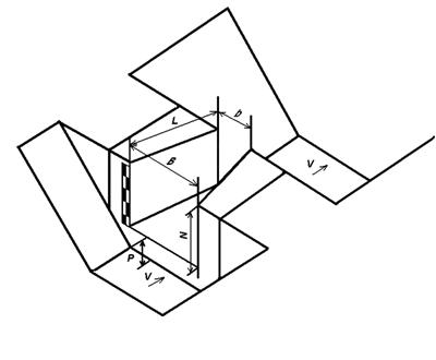
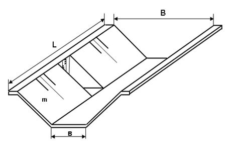
3. Measure the average width of the canal bottom (b), top (В) and constructional depth (h) and determine the length of the rectilinear section;
4. Select the suitable type of a water meter (gauge).
Explanations for each paragraph of the operations:
For the first paragraph: The canal section where a gauging station is planned to be constructed, should be of rectilinear shape, its length is to be at least L = (6-10) * b, where b is the canal bottom width. The section line of the gauging station is to be installed in the middle or a little downstream of the middle of the rectilinear section length at a distance l = 0.5-0.7 * L. It is needed to make sure by visual examination that there is no deposition of bed silts, damage of canal banks and sides;
Longitudinal and transverse cross-sections of the selected section of a canal
For the second paragraph: To examine the water surface and bottom of the reach of both the canal upstream and downstream. Determine the flow streamline regime and give a visual evaluation of irrigation water quality (presence of sediment load) in the site where a gauging station is planned to be constructed;
For the third paragraph: Depending on the results of examination made according to Paragraphs 1 and 2, to select proper types of gauges suitable for water accounting in this cross section. Depending on financial possibilities, availability of local building materials, and other factors, to select the proper type of gauge finally.
Standard gauges for measuring water discharge
The following types of water gauges are adopted as standard devices for measurement of water discharge:
• Weirs with thin wall, of different cross-sections;
• SANIIRI flow-metering crests;
• Venturi flumes;
• Parshall flumes;
• SANIIRI (Yartsev) flumes.
All the above-listed gauges meet the requirements of Standards and Regulations, which enables manufacturing and using such gauges without individual calibration.
Below, we shall consider the most widely used standard weirs of Thompson and Cippoletti and SANIIRI (Yartsev) flumes, which are designed for metering water discharge in the on-farm irrigation network.
Thompson weir (TW)
TW-50 is intended for metering water discharge of up to 50 l/s. TW weir is made both of portable and stationary type. Its framework consists of a triangle-shaped weir with edges converging at an angle of 90о, made of 3-mm-thick sheet steel; a stiffening angle and a gauging rod fastened on the weir wall aslant (45о) or upright (90о). The TW weir crest edge directed to the weir inlet should be sharp, beveled at 45о.
Cippoletti weir (CW)
Cippoletti weir CW-50 (in Russian ВЧ–50) is intended for irrigation ditches with the discharge measurement range from 5 to 80 l/s; CW-75 (in Russian ВЧ–75) is designed for irrigation ditches with the discharge measurement range from 15 to 230 l/s. CW-50 is classified as a trapezoid-shaped weir with a thin wall with side slopes of 1:4. It is made of sheet steel 3-4 mm thick and angles for reinforcing the construction. The weir crest width (b=50 cm) is made to a tolerance of +2-3 mm; other dimensions, to a tolerance of +5-10 mm; the edge of the discharge sluice should be flat, smooth, without dimensions notches and protuberances.
CW-75 is made of 4-mm thick steel; its discharge sluice should be smooth, without notches and protuberances. The basic size of the crest is b= 75 cm, made to a tolerance of + 5 mm; other dimensions, to a tolerance of +10 mm.
The width of TW and CW weir crests is made to a tolerance of +2-3 mm; other dimensions to a tolerance of +5-10 mm; discharge sluice edge should be flat, smooth, without notches and protuberances.
Edge of TW, CW weirs' crest is to be sharp, beveled at 45о, directed poosite to the stream.
The gauging rod is to be manufactured at a specialized plant from metal coated by waterproof paint. Graduation marks and numbers should not be worn away, and the zero points of the gauging rods should coincide with the weir crest level; the entire metal framework is to be painted with anticorrosive paint in three coats.
Requirements for installation of TW and CW weirs:
• the unlined canal section intended for installation of a weir should be rectilinear with a length of no less than L=10 * b, with symmetrical cross-section;
• the unlined canal section (bottom and slopes) should be cleaned from silt, aquatic vegetation, and rubbish keeping symmetric properties;
• a weir should be installed in the middle of the prepared section strictly upright and perpendicularly to the canal axis, cutting into the bottom and slopes of the unlined canal;
• the weir crest should be strictly horizontal; the vertical wall should be perpendicular to the base; the weir axis should coincide with the canal axis;
• the weir crest height P should exceed the maximum canal depth hmax downstream the weir;
• the approach section and the end of the tailrace section of the canal should be made in the form of a hydraulic cutoff wall, i.e. of concrete pouring more than twice as wide and thick as the thickness t of the canal bottom concrete casing;
• if flow velocity exceeds 0.5 m3/s, the canal approach section upstream the weir should be widened, and the bottom should be deepened to slow down the flow velocity.
Gauging station with a Cippoletti weir
Note: To mount weir crest strictly in the horizontal position and to bind its crest elevation to the zero point of the gauging rod, it is recommended to use a leveling instrument or a hydraulic level tube using to this effect a long small-diameter transparent hose filled with water (law of communicating vessels).
Measurement of water discharge by means of weirs
Estimation of water discharge (m3/s) is carried out according to the following working formulae:
For triangular TW weirs

For trapezoidal CW weirs

where:
b is width of weir crest, m;
H is water head above the weir crest, m.
Operation of weirs (TW, CW)
For normal water accounting within the range of tolerable accuracy (σ ± 5%) the following rules must be observed:
• regularly check the horizontality of the crest and verticality of the wall; make sure that the gauging rods’ zero points coincide with the crest level;
• clean the approach section of the canal from silt (crest P should be above the canal bottom in the head race);
• the weir crest must not to be submerged in the upstream part;
• repair (cleaning from sediment load, elimination of defects, painting, replacement of gauging rods, etc.) the weir facility at least once a year.
For small canals in WUAs it is recommended to build SANIIRI flumes, while other flume types (Parshall, Venturi) are not recommended to be built, because they are difficult to make.
SANIIRI water measurement flume (SWMF)
SANIIRI gauge flume (SWMF) represents a short flume with vertical walls converging to the tail-water part and the horizontal bottom. Coupling of the flume with a canal in its head-water and tail-water parts is performed by means of wing walls; at that, a basin is installed in its stilling (bucket) section. Elevation of crest P above the canal bottom is unnecessary. The gauging rod is fastened to the front wall of the flume; the rod zero point should coincide with flume bottom elevation.
SANIIRI gauge flume (SWMF)
Equation of discharge for SWMF at free outflow  is given by:

where:
 is the coefficient of discharge;
b is the width of bucket lip of the throat of the flume (m);
Н is the water depth above flume crest at the head-water section (m);
The working formula is given by:

SANIIRI flume is intended for measuring discharges at free flow. Free flow for SWMF is achieved at h ≤ 0.
Longitudinal profile of SANIIRI flume
SWMF manufacturing and operation requirements
• Displacement of the flume plane or its mouth relative to the approach canal’s axial plane should not exceed 5 mm at the approach canal width Вк < 500 mm. At Вк = (500–1500 mm), it should not exceed 10 mm. And finally at Вк > 1500 mm, it should not exceed 15 mm;
• Declination of the side walls of the throat of the flume from vertical line should not exceed 2 mm per 1 m of the wall height.
• The bottom of the throat or inlet socket of the flume should be strictly horizontal. Declination should not exceed 1 mm per 1 m of the throat length (or width).
• Submergence of the flume bottom at its tail-water part must be avoided.
If SWMF is built properly, water flow comes to the stilling basin in the gauging station’s outgoing section without submerging it, i.e. the condition h ≤ 0 is fulfilled.
Fixed bed
In the water accounting practice, if there is a need of accounting of high flowrate or if flow regime has non-steady nature, a gauging station of fixed bed (FB) type with a gauging rod is to be installed on the straight unlined section of the canal.
To obtain the discharge characteristics Q = f (H) it is necessary to make individual graduation marks “FB” (stands for fixed bed). Fixed bed can be made by using concrete slabs or cast-in-situ concrete at least 5 cm thick to make the lining resistant to mechanical effects and wash-out by water stream.
Fixed bed
Requirements for equipping of FB-type gauging stations
• FB-type measuring section should be provided on the straight section of the canal with uniform flow regime;
• No obstacles (bridge footings, close bend) that may influence the water flow regime at the gauging station section line of should be on the straight section of the canal;
• To keep the cross-section of gauging station section line constant, it is recommended to line the sides and bottom of the canal (concrete belt);
• The canal section for FB should be rectilinear, with permanent rectangular, trapezoidal or parabolic cross-section which allows deviations from average geometrical dimensions (width, overall height of the bed, slope gradient value) at most ± 2 % of the cross-section, with constant bottom slope;
• The beginning of the approach section and end of tailrace section of FB should be made in the form of a hydraulic cutoff wall, i.e. of concrete pouring of more than twice as wide and thick as the thickness of the canal bottom concrete casing;
• A gauging rod should be installed in a special well or niche; the rod zero point should coincide with the canal bottom elevation in the gauging station section line;
• The measuring section must always be clean, free from sediment load and rubbish;
• At operating variable flow regime at FB-type gauging stations it is necessary to carry out check measurements of water discharge after any change of the level.
At canal flow velocity of less than 2 m/s, a permissible length of the canal reach, where mentioned conditions are to be fulfilled, should be at least L = (6 - 8)*В depending on the canal surface width (B).
Parabolic flumes
Parabolic flumes of LR-40; 60; 80; 100 (in Russian ЛР-40; 60; 80; 100) types have gained widespread currency in the irrigation practice. These water conveying facilities can be classified as FB variety. Water metering in these flumes is performed by calibration and getting discharge characteristic Q = f (H).
A calibrated parabolic flume (CPF) is a site (station) equipped and calibrated for carrying out regular water accounting. CPF includes one section of LR flume and measuring section (working) for metering depth and flow velocity, a bridge fixed on it, a stilling well (basin) with a gauging rod or flow-measuring scale marked on the slope. The selected section and adjacent sections of flumes must be in good order with equal gradient.расходомерной шкалой. Выбранная секция и соседние секции лотков, должны быть исправными с одинаковым уклоном.
Source: Guidelines for selecting the type, site, and installation of water meters in the WUA.
IWRM-Fergana Valley Project report, Tashkent, 2010. Executive in charge R.R. Masumov [in Russian]
Monographs and brochures
Papers
Alimjanov A.A. - Management of monitoring of the water use in WUA [in Russian] (2008) 
Hydrometric current meter GR 21M [in Russian]
Ibragimov I.Yu. - Stages of the construction of different-type gauging stations [in Russian] (2008)
Klimenko D.E. - Development of hydrometric current meters in Russia and abroad [in Russian] (2010)
Masumov R.R. - Importance of water accounting in water consumers’ associations [in Russian] (2010)
Masumov R.R. - Current status of the water accounting on rivers and canals [in Russian] (2012)
Masumov R.R. - Gauging station calibration and error budgeting [in Russian] (2012)
Masumov R.R. - Deriving the flow-rate equation by using a PC [in Russian] (2012)
Masumov R.R. - Water source monitoring, its efficient use and redistribution [in Russian] (2012)
Rasulov, U.R. Low water flow measurement methods and instruments [in Russian] (2009)
Regulatory and procedural guidelines and reference information
Directions for monitoring and metering of water discharge by means of a weir [in Russian] (2007)
Instruction booklet for builders of water meters in WUA [in Russian] (2008)
Water metering manual for main canal hydrometering specialists [in Russian] (2006)
Reference book for water accounting for hydrometering specialists in WUA [in Russian] (2005)
Technical standards
GOST 25855-83. Surface water level; and discharge. General requirement for measurement [in Russian]