To the beginning of the section
To equip vertical drainage wells, one should as a rule use centrifugal well pumps with submersible motors of ETsV (in Russian ЭЦВ) type.
When choosing the equipment, one should consider the following technical and operating characteristics of it:
• static level of water in the well;
• well characteristics that express the relationship between the dynamic drawdown of groundwater level in the well and well output/discharge as well as the values of design dynamic drawdown parameters Sc,d and well output/discharge Q.
• well depth, diameter of the casing string (dead and filtering sections), filter placing space;
• elevation of the wellhead and center of the pipe lateral’s discharge outlet;
• required positive/excess head when operating for the closed network of pipes.
The required head can be calculated by the following formula:
Ht = Sc,s + Sc,d + D DL + He + lf
where:
Sc, s is the static well water drawdown, m;
Sc , d is the dynamic well water drawdown, m;
D DL is the difference between the geometric elevations of the wellhead and pipe lateral’s discharge outlet, m;
He is the positive/excess head required for operation of the closed network of pipes, m;
lf is head losses to friction along the pipeline and local losses in fittings, m;
lf = ll + lx
where:
ll stands for friction losses; determined from nomographic chart 1;
lx stands for the losses in fittings; determined from nomographic chart 2.
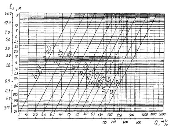
Chart of the head losses in water-raising pipes per 100 m of its length
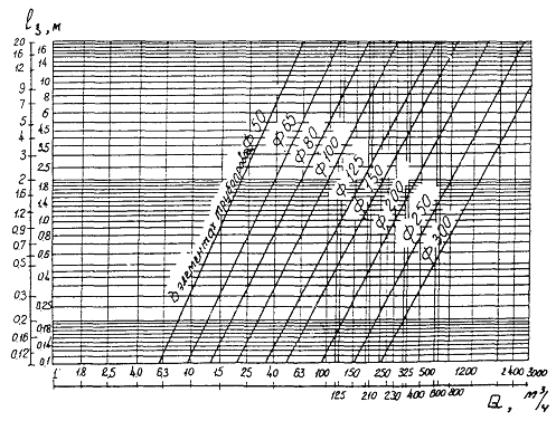
Chart of the head losses in the pipeline components
(of standard well equipment including: 6-8 pipe sections, flexible bend 90°, slide valve,
elbow bend 90°, pipeline outlet)
Selection of a pump should be based on the use of its discharge characteristics only in the domain of high efficiency values:
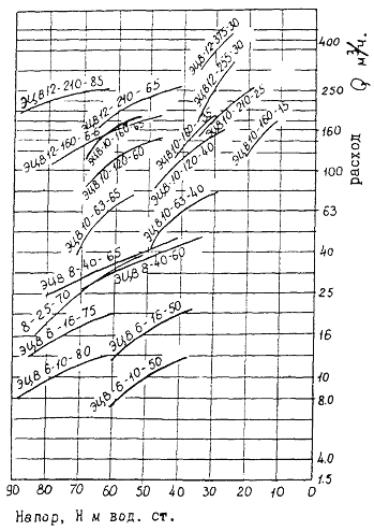
Characteristics of ETsV type submersible motors
Developed pumping head Нd of the pump selected at a discharge of Q = Qd should be not less than the required.
Ht ≤ Нd
The best system operation mode will be provided when the optimum modes of a given pump and well match as follows
Qobs = Qd and Ht = Нd.
A pump with a head of up to 5% lower than the required can be used. At that, the following measures should be provided for:
• use pipes of greater diameter for the outlet pipeline;
• the values of the design parameters Qd and Hd should be lowered within admissible limits.
In case the operating range of the discharge characteristics is higher than the operating constraints of the well, one of the following regulation methods needs to be provided for:
• throttling of water flow;
• pump impeller trimming;
• removal of pumping steps;
• combined method.
A certain regulation method is selected based on the technical & economic assessment given the minimum cost of 1 m3 of pumped water. The cost of 1 m3 of pumped water is calculated by the following formula:
where:
t is calendar time within a year (hours);
h is well work ratio;
Bc cost of electric power (cent/kW);
hm is pump efficiency after regulation, %;
hn is motor efficiency;
V is the volume of water pumped;
U is additional cost of regulation.
First, a regulation method is selected by the following formula:

where:
Ha,1 is the head of one step;
j is the number of steps:
a) at  it is necessary to leave one step and trim the impellers;
b) at  it is necessary to leave one step without trimming the impeller;
c) at  it is necessary to leave two steps and trim the impeller of one or two steps;
d) at  it is necessary to leave two steps; etc.
In case the power consumed by the pump is reduced due to trimming of the impeller diameter or removal of a pump step, the submersible electric motor should be replaced by a smaller one out of the range of standard sizes. The required pump power can be specified by the following formula:

where:
h т, b is the submersible pump efficiency.
Regulation by throttling is acceptable with a proviso that

The efficiency of the submersible pump at throttling is determined as follows:

Trimming of the impeller’s outer diameter will result in the decrease in the discharge characteristics Q-H of the pump. After trimming, the consumed power Р will reduce as well as the efficiency h т to a considerable extent. The values of corresponding parameters with trimmed impeller are determined through the following formula:
where:
D ; Dn are respectively the diameters of normal and trimmed impellers;
α, β and γ are conversion factors specified from the nomographic chart below.
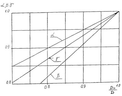
Dependence of conversion factors from trimming
of the impellers of submersible pumps
The head of multistep pumps lowers in proportion to the number of the removal of pump steps. The pump efficiency remains almost constant.
The best regime of the equipment can be achieved if the head-capacity curve, after the removal of a step, passes through a targeted point; otherwise, it would be required to lower excessive head by regulation.
The combined regulation method includes removal of a step with simultaneous trimming of the impeller and replacement of a submersible electric motor by one of less rated capacity.